Triode replacement (en)

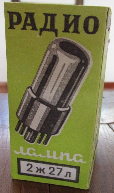
This small project explains how to build a replacement for all European 4-pin tubes type A410 or similar, with a filament voltage of 4V and an anode voltage not exceeding 90V. The basis for this replacement is the very common 2J27L Russian pentode you can buy for very little money on ebay.


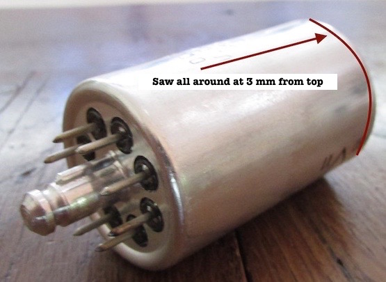
First you need to cut the external aluminum case with a jigsaw at about 3 mm from the top. I suggest to turn the tube as the blade enters inside the case to avoid any damage to the glass bulb. The tube can then be extracted very easily.


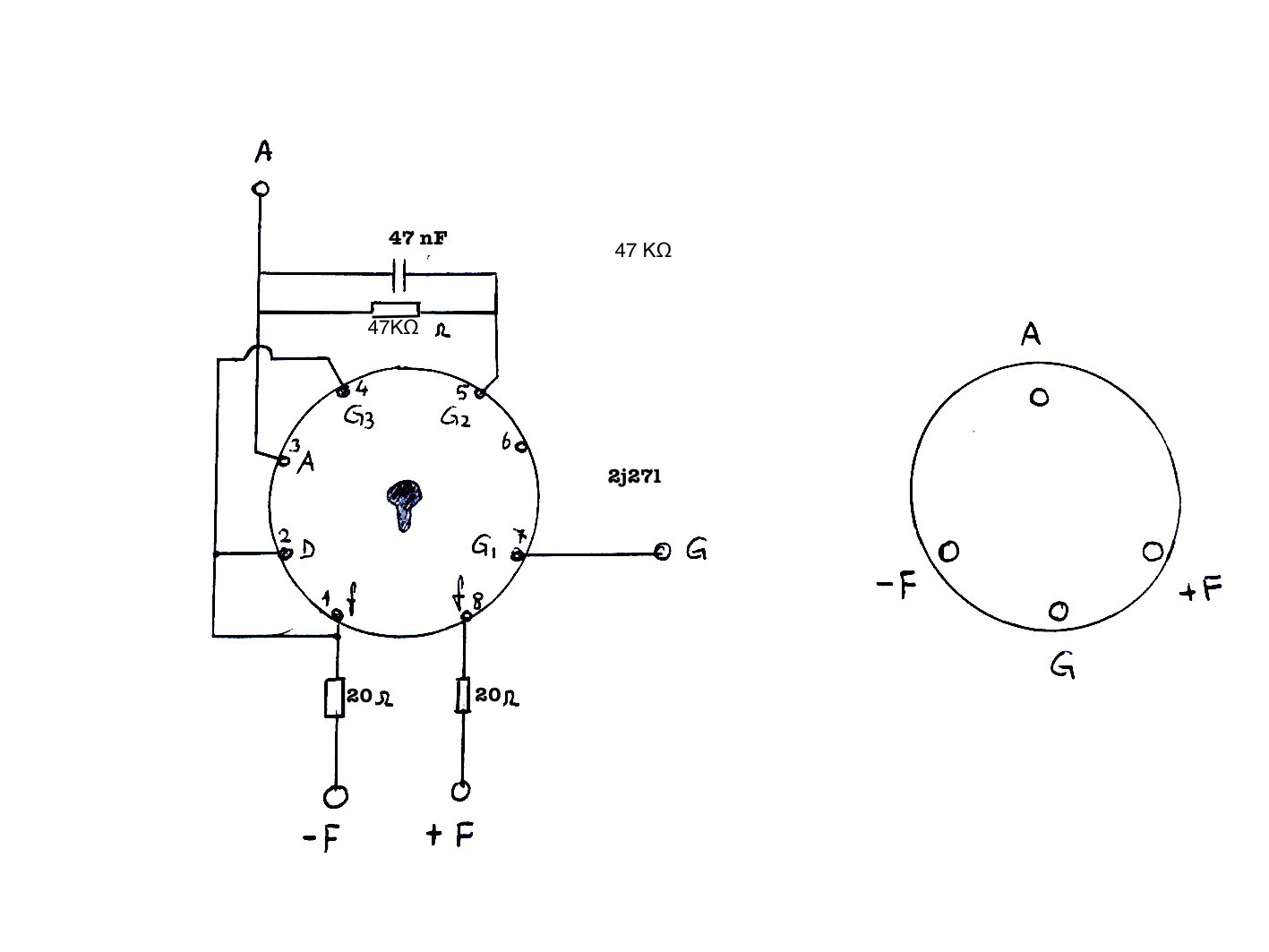
This is the diagram. Pins are seen from below. Two resistors from 20 to 22 ohms reduce the filament voltage from 4V to 2.2V needed for the pentode. The screen grid (G2) is connected to the anode (A) through a 47 kohm resistor and a 47 nF capacitor. This allows the pentode to work configured as a triode avoiding excessive anode current. The capacitor should have a working voltage of not less than 100V.


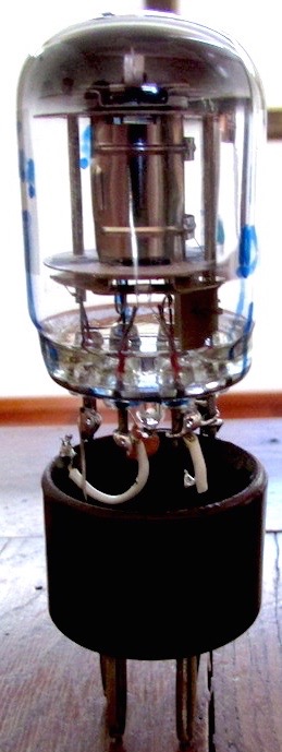
Here you can see the tube installed on the base. The resistors and the capacitor are in the base


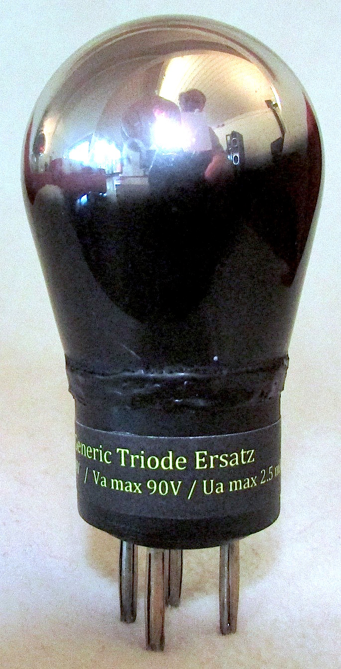
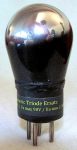
This is the end result. I used the glass bulb of an old faulty tube properly cut and glued on the base with epoxy resin which I then painted in black. This tube can be used as high and low frequency amplifier, as a detector, etc …

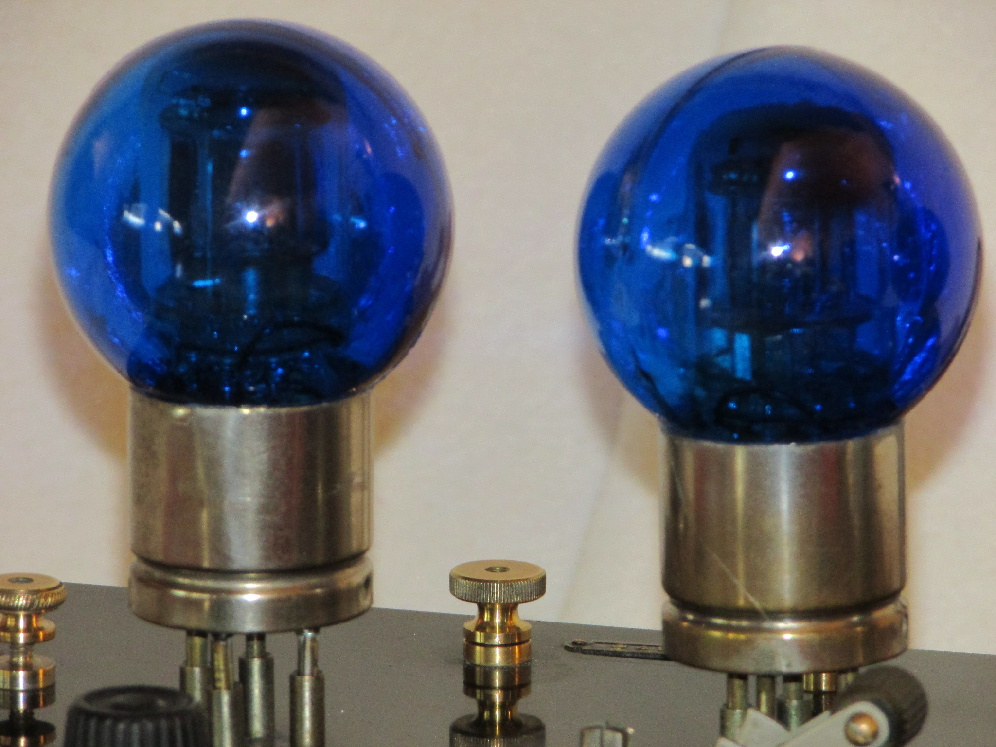
Even using cheap plastic Christmas balls is not too bad…


My L.G.M. Radiovalise visible and audible in the “tube radios” section is equipped with this tube as detector, My Lemouzy H.D.4 works with 4 of these tubes. My advice: check the result before you close and glue the tube.

Rimpiazzo per triodo (it)


Questo piccolo progetto spiega come costruire un rimpiazzo per tutte le valvole europee a 4 piedini tipo A410 o simili, con tensione di filamento da 4V e tensione anodica non superiore a 90V. La base per questo rimpiazzo è la comunissima 2J27L, pentodo russo che si trova per pochi soldi su ebay.


Prima di tutto bisogna tagliare con un seghetto la scatola esterna in alluminio a circa 3 mm dalla cima. Consiglio di ruotare la valvola man mano che la lama entra all’interno per evitare eventuali danni al bulbo in vetro. La valvola può quindi essere estratta molto facilmente.


Questo è lo schema. I pin dei tubi sono visti dal di sotto. Due resistenze da 20 a 22 ohm riducono la tensione per il filamento da 4V ai 2,2V necessari al nostro pentodo. La griglia schermo (G2) viene collegata all’anodo (A) tramite una resistenza da 47 kohm ed un condensatore da 47 nF. Questo permette al pentodo di lavorare configurato come un triodo evitando però un’eccessiva corrente anodica. Il condensatore dovrà avere una tensione di lavoro pari o superiore a 100V.


Qui vediamo valvola installata sullo zoccolo. Le resistenze ed il condensatore sono al suo interno


Questo è il risultato finale. Ho utilizzato il bulbo in vetro di una vecchia valvola difettosa opportunamente tagliato ed incollato sulla base con resina epossidica che poi ho verniciato in nero. Questa valvola può essere utilizzata come amplificatore di alta e bassa frequenza, come rivelatore, ecc…
Persino della bocce in plastica per alberi di Natale fanno la loro figura…
La mia L.G.M. Radiovalise visibile ed ascoltabile nella sezione “tube radios”  è equipaggiata con questa valvola al posto della rivelatrice e pure la Lemouzy H.D.4 funziona con queste valvole. Alla prima messa in funzione sarà bene verificare che la corrente anodica non superi 2,5 – 3 mA. Il mio consiglio: controlla il risultato prima di incollare la valvola.

Social media & sharing icons powered by UltimatelySocial